Nous sommes responsables de la construction-----nous sommes responsables de la fabrication-----nous sommes responsables de la formation

A Presse plieuse CNC is a sheet-metal bending machine whose ram, back gauge and deflection compensation are positioned by a numerical controller. Y1/Y2 control ram depth, X and R place the bend line, Z axes move the gauge fingers sideways, and crowning keeps the angle constant along the bend length. Most shops need fewer axes than they are quoted.
A press brake forms a bend by pushing a punch into a V-die. The depth the punch travels into the die sets the angle; where the sheet sits against the back gauge sets the flange length. Everything “CNC” adds is about controlling those two things automatically and repeating them part after part.
The term hydraulic press brake describes how the ram is driven, not how it is controlled. On a hydraulic machine, two cylinders push the ram down. On a pure electric machine, servo motors drive the ram through ball screws or similar mechanisms. Both can be CNC.
Older and entry-level machines are often NC with torsion-bar synchronisation: a steel shaft mechanically ties both ends of the ram together so they move as one. Compared with torsion-bar synchronised NC press brakes, an electro-hydraulic CNC machine controls each side of the ram independently, which is what lets it correct for an off-centre part or a slightly tilted die. For simple brackets in mild steel, a torsion-bar machine is still a workable, cheaper choice. It runs out of capability when the work needs programmable ram tilt, multi-step back gauge moves or stored programs that an operator can recall without re-teaching.
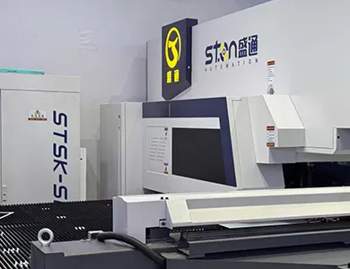
An “axis” on a press brake is any motion the controller positions on its own. The count on a quotation (4+1, 6+1, 8+1) tells you how many of those motions exist. It does not tell you which ones, and that is what matters.
| Axis | What physically moves | What it controls on the part | Who actually needs it |
| Y1 / Y2 | Left and right sides of the ram | Bend angle (via punch depth) and ram parallelism | Every CNC press brake |
| X | Back gauge, front-to-back | Flange length / bend line position | Every CNC press brake |
| R | Back gauge fingers, up and down | Gauging height when flanges or tool heights change between bends | Boxes, return flanges, staged tooling |
| Z1 / Z2 | Each gauge finger, left to right | Finger position along the bend line | Varying part widths, multiple tool stations in one setup |
| X1 / X2 (Delta X) | Each finger independently, front-to-back | Non-parallel bend lines | Tapered or angled flanges |
| V (crowning) | Table or die holder profile | Angle consistency over the full length | Long or high-tonnage bends |
| Sheet followers | Front supports that rise with the sheet | Prevents large sheets whipping or sagging | Large, thin panels; single-operator work |
Two practical notes before you compare quotations.
First, axis lettering is not universal. Controllers and manufacturers sometimes assign letters differently, and some count crowning as an axis while others list it separately (the “+1” in “6+1”). Ask for the axis list in writing.
Second, Y1/Y2 and X do most of the work. Every axis beyond them saves time on specific part geometries. If your parts do not have those geometries, the axis sits idle.
On a long machine, the “+1” is often the crowning axis, and it frequently has a larger effect on part quality than adding Z or Delta X. A 6+1 configuration without CNC crowning on a long bed can give worse angle consistency than a 4+1 machine that has it.
Crowning: What It Corrects and What It Cannot
Under load, the ram and the table both bow slightly. The middle of the bend sees less punch penetration than the ends, so without correction the angle in the centre comes out more open than at the ends. The longer the bend and the higher the tonnage, the more visible this becomes.
Crowning pre-shapes the table (or die holder) so that, under load, the punch-to-die gap stays even from end to end. The two common methods:
Both STON press brake lines covered below use a mechanical compensation system.
What crowning will not fix is just as important for buyers. The Fabricator notes that CNC crowning compensates for symmetric deflection, and that standard crowning is sufficient when material properties are uniform along the part. If the sheet varies in thickness or hardness along its length, if the die is worn more in the centre than at the ends, or if grain direction changes between batches, the angle will still drift. Crowning corrects the machine, not the material.
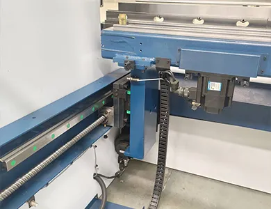
These two words are used interchangeably in sales literature. They mean different things on the shop floor.
A press brake can be highly repeatable and still inaccurate (consistently 1° open, for example), which a program correction fixes. It can also be accurate on the first part and then drift, which no program correction fixes.
Here is the edge case that trips up many buyers: a grating ruler (linear scale) gives the controller closed-loop feedback on ram position. It does not measure part angle. Closed-loop Y-axis control removes positioning error from the machine side. The remaining angle variation comes from springback, which depends on the sheet itself. Two sheets of the same nominal grade and thickness, cut from different coils, can spring back differently at the same ram depth.
Many fabrication drawings default to the general tolerances of ISO 2768-1 rather than stating a tolerance on each bend. For the “m” (medium) class, permissible angular deviations depend on the length of the shorter leg:
| Shorter leg length (mm) | ISO 2768-1 class m angular tolerance |
| up to 10 | ±1° |
| over 10 to 50 | ±0°30′ |
| over 50 to 120 | ±0°20′ |
| over 120 to 400 | ±0°10′ |
| over 400 | ±0°5′ |
If most of your drawings sit in the short-leg rows, the limiting factor is usually material consistency and tooling condition, not the number of axes.
When we review drawings with customers before an order, this is the check we suggest running on a demo or sample machine:
If the centre-versus-end difference is large, look at crowning. If the two sets sit apart but each set is tight, the machine is doing its job and the variation is coming from the material.
STON builds two press brake series: the PBS Series Electro-Hydraulic Servo Press Brake and the PBE Series Pure Electric Press Brake. Both are designed and manufactured in STON’s own Qingdao factory, from frame welding and stress relief to assembly and inspection.
| Fonctionnalité | PBS electro-hydraulic servo | PBE pure electric |
| Ram drive | ESTUN servo motor with hydraulic system | Direct-drive servo motor; no hydraulic oil |
| Controller | DELEM 53T, 58T, 66T or 69T; Italian ESA optional | Intelligent CNC system with multi-axis linkage and program storage |
| Deflection compensation | Mechanical compensation system | Mechanical deflection compensation system |
| Ram position feedback | Grating ruler, real-time closed loop | Grating ruler, full closed loop |
| Cadre | High-strength welded steel; annealed, shot-blasted, aged | Integral welded; annealed, shot-blasted, aged |
| Guides / drive train | Precision linear or rolling guides | Linear rolling guides with heavy-duty ground lead screws |
| Electrical components | ESTUN and Siemens | Siemens |
| Back gauge | Multi-axis CNC linkage | Multi-axis CNC linkage, multi-segment programming |
| Operator safety | Laser protection device, stops on intrusion | Laser safety protection system |
| Automatisation | Expandable to robotic loading/unloading | Compatible with most robotic arms on the market |
How to choose between them comes down to tonnage, maintenance and the work environment. The PBS line covers a tonnage range up to the 320/4100 model and carries 130 to 500 L of hydraulic oil depending on size, which means oil changes, filter service and attention to oil temperature. The PBE line removes the hydraulic circuit entirely, which simplifies maintenance and eliminates oil leaks near clean parts such as kitchen equipment or appliance panels. Ask for the PBE tonnage and length range for your part before comparing, since it is quoted per configuration.
Every machine is quoted to configuration. The price is driven mainly by:
For more information, please nous contacter.Send your part drawings, material grade, thickness range and target monthly output, and the quotation will list the axis configuration with a reason for each axis.
How many axes does a CNC press brake need?
For most job shops, Y1, Y2, X and R plus crowning cover the majority of work. Add Z1/Z2 for mixed widths or multi-station setups, and X1/X2 only if you bend tapered flanges.
Is a hydraulic press brake less accurate than an electric one?
Not inherently. Both can use closed-loop ram feedback. The practical differences are maintenance (oil versus no oil), operating environment and the tonnage range each design covers.
Does a grating ruler guarantee consistent bend angles?
No. It measures ram position, not the bend angle. Angle variation from material springback still has to be handled through program correction, material control or a separate angle measurement system.
Do I need crowning on a short press brake?
On short beds and light tonnage, deflection is small and manual or fixed crowning is often enough. On long beds such as 3,200 or 4,100 mm, CNC crowning has a measurable effect on centre-to-end angle consistency.
What is the difference between NC and CNC press brakes?
NC machines usually use mechanical (torsion-bar) ram synchronisation with simpler back gauge control. CNC machines control each side of the ram and multiple back gauge axes independently, and store complete bending programs.


Que vous modernisiez une ligne existante ou que vous lanciez un nouveau projet, STON personnalisera une solution CNC pour votre production.


