Somos responsáveis pela construção----- somos responsáveis pelo fabrico----- somos responsáveis pela formação

Uma linha de produção de armários liga o desenrolamento, o nivelamento, o corte a laser ou puncionamento por torre, a dobragem de painéis e o empilhamento num único fluxo de material controlado. Para um armário de distribuição de 1,5 mm em aço laminado a frio, preveja aproximadamente 3,5 minutos de tempo de linha por corpo de armário, três a quatro operadores por turno em vez de nove ou dez, e 35 a 45 metros de comprimento de piso, incluindo os buffers.
A maioria das fábricas de armários não precisa das seis. A ordem importa mais do que a quantidade.
Desenrolamento. O desenrolador desenrola a bobina de tira e estabelece um equilíbrio de material sincronizado com o nivelador. STON’s a base e o corpo do desenrolador são estruturas soldadas submetidas a tratamento de envelhecimento térmico. A capacidade da bobina é ≤10 T.
Nivelamento. Rolos niveladores em 40Cr, com rolamentos autocompensadores ou de agulhas nos rolos de trabalho. A precisão de nivelamento divulgada é de ±1 mm/m², com precisão diagonal ≤1 mm/2000 mm. Esta estação é o que torna a alimentação por bobina viável — uma chapa não nivelada não manterá o ângulo de dobra em uma dobradeira de painéis.
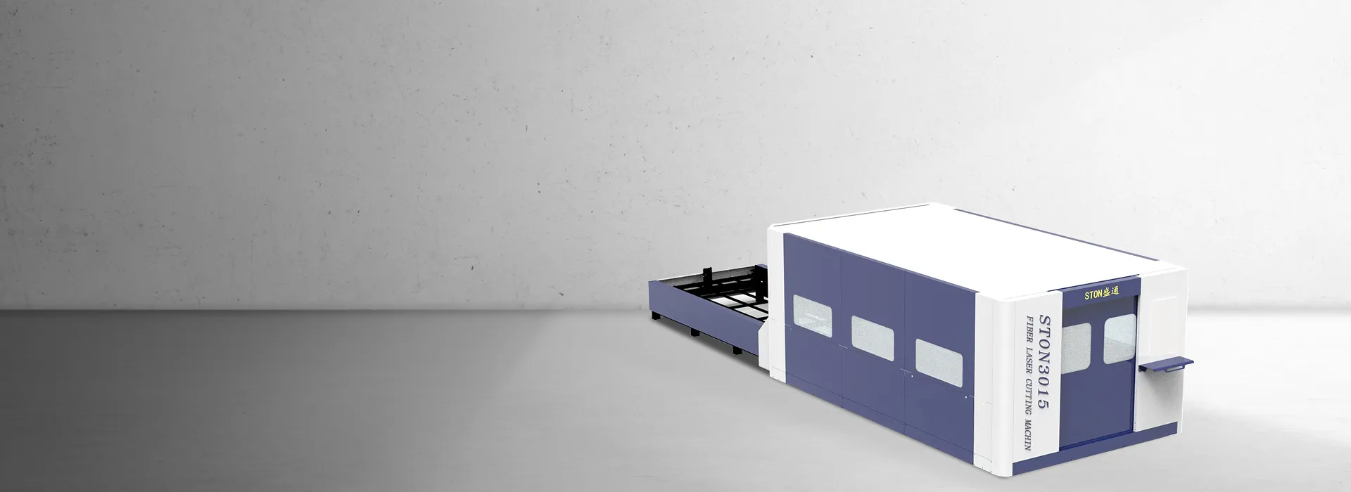
Corte a laser. Laser de fibra, de 1 kW a 6 kW, com base de dados de parâmetros de corte e ajuste de parâmetros em tempo real durante o corte. Esta é a sua estação de corte inicial para portas de armário, painéis laterais e painéis traseiros com recortes.
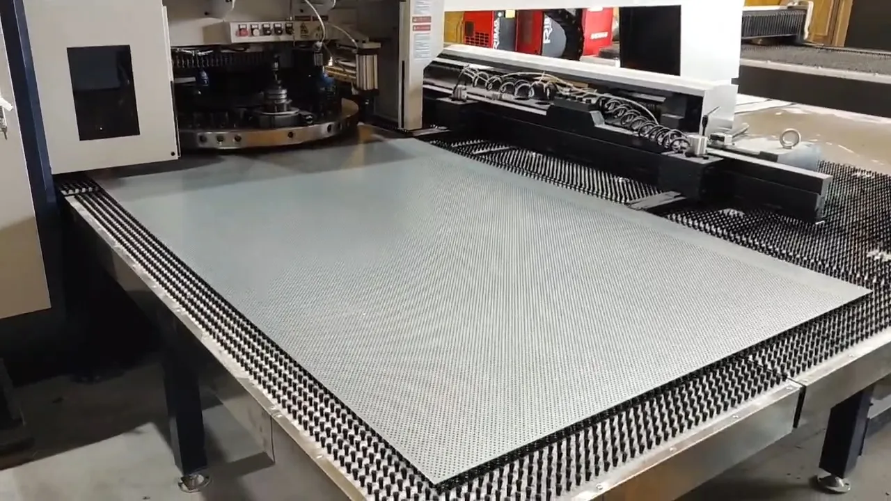
Puncionamento com torre. A estação que se justifica quando as suas peças têm persianas, nervuras, gravação em relevo ou um elevado número de furos. Puncionamento, corte, conformação, formação de persianas e prensagem de nervuras numa única torre.
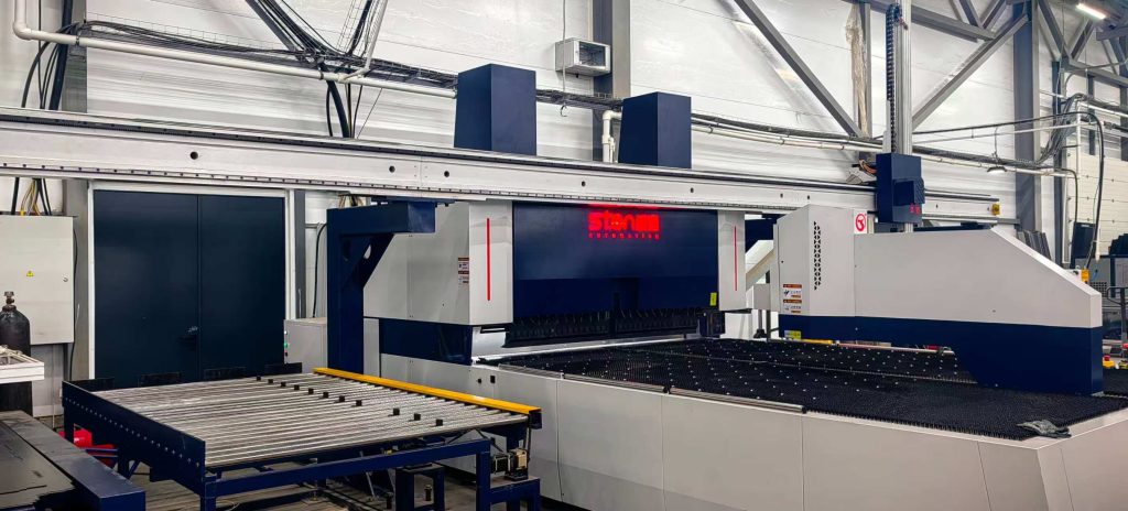
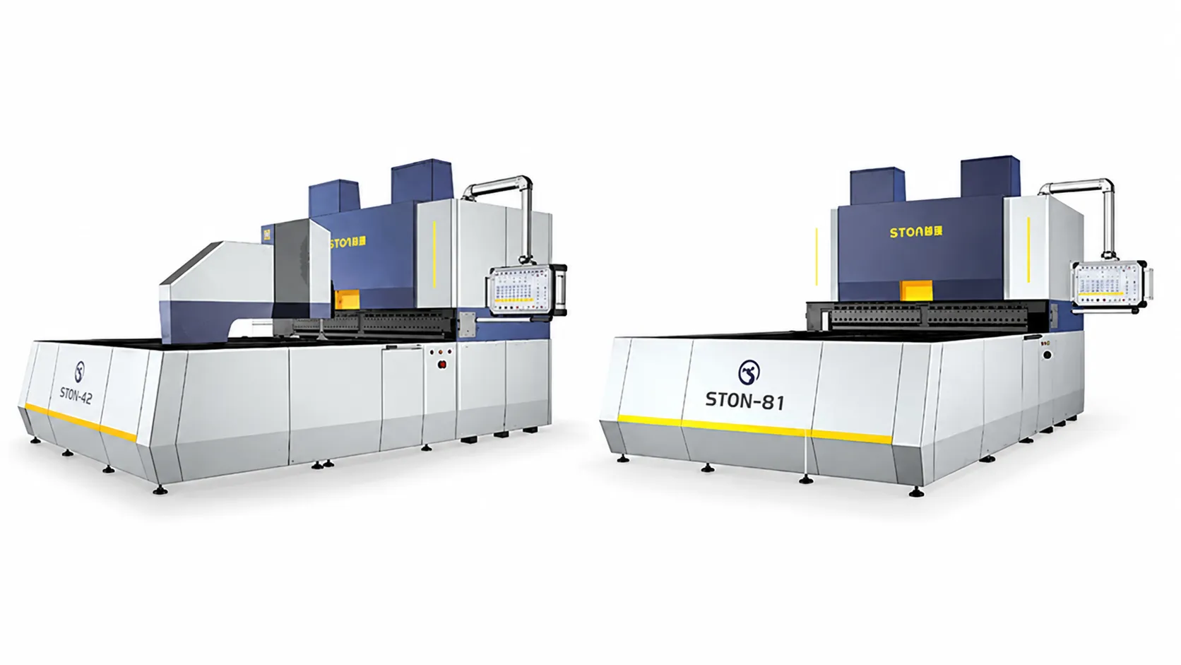
Dobragem. Uma dobradeira de painéis CNC realiza dobras multiangulares num painel numa única fixação, com compensação de ângulo e troca de programa entre produtos.
Empilhamento e, opcionalmente, soldagem. Uma célula robotizada de soldagem com posicionador, dispositivos de fixação e rastreamento de junta pode ser acoplada para soldagem de topo, filete e ponto no corpo do gabinete.
Para uma fábrica de gabinetes que opera com uma família de SKU dominante, as estações 1, 2, 3 e 5 formam a linha mínima viável. Elimine a torre e você perde as venezianas. Elimine o nivelador e você perde a consistência de dobra, o que não é uma perda recuperável mais adiante no processo.
Considere um invólucro padrão de distribuição de baixa tensão. Oito peças de chapa por corpo: dois painéis laterais (1.800 × 600), painel traseiro (1.800 × 800), porta (1.800 × 800), topo e base (800 × 600 cada) e uma placa de montagem (1.600 × 700).
Net blank area comes to about 7.12 m² per cabinet. At 11.775 kg/m² for 1.5 mm steel, that is 84 kg of finished material per body.
Coil-fed nesting on a 1,500 mm strip lets you run the two 600 mm side panels two-up and the 800 mm panels one-up with the balance recovered by small parts. Working at 88% utilisation, gross consumption is 8.09 m², or 95 kg per cabinet. One 10 T coil therefore yields approximately 105 cabinet bodies.
Compare that against sheet-fed blanking from 1,250 × 2,500 sheets, where a mixed cabinet nest realistically lands near 78% utilisation. Gross consumption rises to 9.13 m² and 107.5 kg. The difference is 12.2 kg per cabinet, about 11%. At 25,000 cabinets a year, that is 305 tonnes of steel. Nobody in the SERP publishes this number, and it is frequently larger than the labour saving.
| Position | Station | STON Reference | Published Footprint (L × W) | Height |
|---|---|---|---|---|
| 1 | Coil Car + Uncoiler | Line-integrated, ≤10 T | Not published in product tables ⁽¹⁾ | — |
| 2 | Leveler | Customised to thickness/accuracy | Not published in product tables ⁽¹⁾ | — |
| 3 | Unidade de corte a laser | STON-3015L (1–6 kW) | 4,500 × 2,600 mm (single-table 3015 standalone) | — |
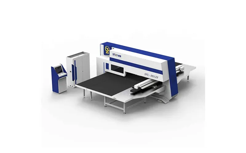
| 4 | Prensa de punção de torre | SF Series servo | 5,200 × 5,000 mm | 2,230 mm |
| 5 | Máquina de dobrar painéis CNC | Press Arm Type, C(2000) casting | 5,580 × 2,700 mm | 3,100 mm |
| 6 | Unload / Stacking | Truss or Bronte robotic arm | Not published in product tables ⁽¹⁾ | — |
Uncoiler, leveler and stacker lengths are set by coil weight, leveling accuracy target and buffer sizing, and are issued on the project layout drawing rather than in the standard product tables. The three published machine footprints alone total roughly 15 m of length. Adding coil handling, leveling, inter-station buffers and stacking, 35 to 45 m of total line length is the planning figure to reserve. Confirm against the layout drawing before pouring foundations.
Working height across the coil section is +800 mm, which sets your operator platform and buffer table heights.
One layout decision that gets made too late: whether the laser and the turret sit in series on one flow, or in parallel branches fed from a common buffer. Series is simpler to control and cheaper. Parallel is what you want if your part mix splits into “high hole count, simple outline” and “complex outline, few holes” — a split that describes most cabinet plants running both bodies and vented doors.
This is the section to hand to your process engineer.
Coil and material envelope (Uncoiling–Leveling–Laser Cutting line)
| Parâmetro | Valor |
|---|---|
| Matéria-prima | Chapa de aço laminado a frio, chapa galvanizada, aço inoxidável |
| Espessura da chapa | 0,5–2,0 mm (aço inoxidável ≤1,5 mm) |
| Largura da placa | 1.000–1.500 mm ⁽²⁾ |
| Peso da bobina | ≤10 T |
| Diâmetro interno da bobina | φ508–630 mm ⁽³⁾ |
| Diâmetro exterior da bobina | φ1.000–1.600 mm |
| Precisão de nivelamento | ±1 mm/m² |
| Precisão diagonal | ≤1 mm/2.000 mm |
| Velocidade de rosca | 5 m/min |
| Line Speed | 0–12 m/min, adjustable |
| Running Height | +800 mm |
| Fonte de alimentação | 3φ AC 400 V ±5%, 50 Hz ±2% |
| Air Pressure / Flow | 0.5–0.6 MPa / |
STON’s line technical parameter table states 1,000–1,500 mm; the company product overview states 200–1,500 mm. Both figures are reproduced here. Confirm the coil width range for your specific configuration with STON engineering before finalising nesting. ⁽³⁾ The line parameter table states φ508–630 mm; the product overview states Ø470–630 mm. Confirm against your coil supplier’s mandrel specification.
| Modelo | Max. Bending Size (mm) | Max. Bending Height (mm) | Max. Thickness at Full Bend | Eixos servo | External Dimensions (cm) |
|---|---|---|---|---|---|
| A (1000) Welded | 1,000 × 1,000 | 170 / 300 / 400 | CR 1.5 / SS 1.0 | 15 | 425 × 160 × 255 |
| B (1400) Fundição | 1,400 × 1,250 | 170 / 300 / 400 | CR 2.0 / SS 1.2 | 15 | 450 × 206 × 290 |
| C (2000) Elenco | 2,000 × 1,500 | 170 / 300 / 400 | CR 2.0 / SS 1.2 | 15 | 558 × 270 × 310 |
| D (2500) Casting | 2,500 × 1,500 | 170 / 300 / 400 | CR 2.0 / SS 1.2 | 15 | 615 × 308 × 310 |
| D+ (2800) Fundição | 2,800 × 1,500 | 170 / 300 / 400 | CR 2.0 / SS 1.2 | 15 | 630 × 338 × 310 |
Model designations appear as A / A+ / B / B+ / C / D / D+ in the product tables and as A2 / B2 / C2 / D2 / F2 on the official product page. A maximum bending length of 4,100 mm also appears in company overview material against 2,800 mm in the model table, and a ±0.01 mm accuracy claim appears against the ±0.1 mm/m dimensional accuracy in the same table. Treat the model table as governing and request written confirmation of series naming, maximum length and accuracy basis on your quotation.
For the 1,800 × 600 side panel in this example, C (2000) covers the envelope. The welded frame is rated CR 1.5 mm at full bend, which puts a 1.5 mm cabinet panel exactly at the ceiling. Specify the cast frame instead. The margin costs money on the quotation and saves it over five years of tool and angle stability.
Turret punch press, SF Series servo
Maximum turret speed 40 rpm; machining accuracy ±0.1 mm; maximum load 150 kg; combined power consumption approximately 3–5 kW; air 0.55 MPa; 380 V ±5%; external dimensions 5,200 × 5,000/5,500/6,500 × 2,230 mm. Table structure is a brush and omnidirectional steel ball composite, which is the detail that governs scratch rate on pre-painted or brushed stainless cabinet faces.
The mechanical JT Series runs 30 rpm turret speed at ≤2 kW combined consumption. Lower energy, lower flexibility.
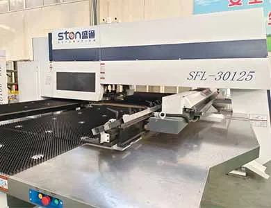
If your part mix genuinely needs both punching and contour cutting on the same part in one clamping, the SFL punch-laser combined machine handles it: 300/400 kN (30/40 T) punching force, “O” type closed frame, X-axis 2,500 mm in one position and up to 5,000 mm with secondary positioning, Y-axis 1,250/1,500 mm, step pitch 405 times/minute at 5 mm, and a die layout of 16A, 11B, 3C, 2D including 1B and 1C rotary stations. STON states it occupies approximately 40% less space than a separate punch press plus laser cutter, and removes the handling, re-clamping and re-alignment time between them.
The station that limits a cabinet line is almost never the punch press. It is either the laser or the bender, and which one depends on hole count versus bend count in your specific part family.
Here is the model for the eight-part cabinet body above. Every assumption is marked.
Laser station. Cut path per cabinet set: blank perimeters total approximately 30.2 m; internal features (DIN rail cutouts, fixing holes, cable entries, ventilation) add roughly 12 m; shared edges in coil nesting recover about 4 m. Net ≈ 38 m.
Assumption: effective cutting speed for 1.5 mm cold-rolled steel at 3 kW falls in the 12–20 m/min band under normal parameters. Using 15 m/min for planning: 2.53 min of cutting. Add 25% for piercing, rapid traverse and indexing: ≈ 3.2 min per cabinet set. Verify against the cutting-parameter database supplied with the machine, not against this article.
Turret station. Approximately 180 hits per cabinet set for fixing holes, louvers and cutouts.
Assumption: 200–300 effective hits/min including axis moves. That gives 36–54 s of punching, plus sheet handling. ≈ 1.2 min per cabinet set. This station has spare capacity in this example. It becomes the bottleneck the moment you add a louvered ventilation door: 800 louvers pushes the same station past 4 minutes.
Bending station. Approximately 36 bend cycles per cabinet set (four edges with return flanges on the two sides, back and door; single flanges on top, bottom and mounting plate).
Assumption: 2.5–3.5 s per bend cycle including axis repositioning, and 8–12 s per part for load and unload with truss or robot handling. That gives 90–126 s of bending plus 64–96 s of handling. ≈ 2.6–3.7 min per cabinet set. STON’s tables publish 15 servo axes and the 0–180° range but not a per-bend cycle figure; request a simulated cycle time against your own DXF files before committing to a throughput number.
| Station | Cycle per Cabinet Set | Utilisation at Line Rate |
|---|---|---|
| Uncoil + Level | Regido pela velocidade de linha de 0–12 m/min; ~5,4 m de bobina por armário | Não limitante |
| Corte a Laser (3 kW) | 3,2 min | Gargalo |
| Puncionamento por Torre (SF) | 1,2 min | 34% |
| Dobragem de Painéis (C2000) | 2,6–3,7 min | 81–100% |
| Empilhamento | Absorbed by buffer | Não limitante |
Line output. Bottleneck 3.2–3.5 min gives 17–18 cabinet sets per hour theoretical. At 85% availability, which is the realistic planning figure once you account for coil changes, program changes, nozzle and lens maintenance and tool changes, output is 14–15 sets per hour, or 115–120 cabinet bodies per 8-hour shift.
Single shift, 250 working days: approximately 28,750 bodies a year. Two shifts: 57,500.
A note on how this differs from what the market publishes. Compared with the European line-builder category, which typically advertises a single headline figure such as seconds per part or products per minute, the number above is deliberately built from station cycles multiplied by an availability factor. A six-second headline figure describes one station running one part under ideal conditions. It is not a line rate, and quoting it back to your board as a capacity plan will cost you credibility when the line commissions.
A production line is not a machine. Under Machinery Directive 2006/42/EC, linked machinery placed on the EU market as a functional unit is treated as an assembly of machinery, which means the line as installed requires its own risk assessment, technical file and Declaration of Conformity — not simply a folder of CE certificates for individual stations. Regulation (EU) 2023/1230 now governs new placements.
Ask specifically for:
PEDRA‘s machines carry ISO and CE certification, and safety hardware including laser protection devices with real-time area monitoring and immediate stop, over-tonnage protection on the mechanical turret, and fully enclosed rear guarding on the flexible edge bending machines. Certification of the individual machine is the starting point. The assembly file is what your factory inspector will ask for.
Q: What throughput should I actually promise my customers after installing a cabinet line?
A: Use the bottleneck station cycle multiplied by 0.85 availability, then apply a further 0.9 factor for the first six months while your programmers build the parameter library. For the 1.5 mm distribution cabinet example, that means promising 100–105 bodies per shift in year one against a theoretical 17–18 per hour.
Q: Can one line handle both 0.8 mm galvanised and 2.0 mm cold-rolled steel?
A: Within the published 0.5–2.0 mm envelope, yes, but not without consequence. Leveling roller settings, cutting parameters and bend compensation all change, so treat each thickness as a separate setup with its own changeover time. At 2.0 mm cold-rolled on the panel bender, you need the cast frame; the welded frame is rated CR 1.5 mm at full bend. Stainless is capped at 1.5 mm on the coil line and SS 1.2 mm at full bend on the cast panel bender.
Q: How much floor space do I need to reserve?
A: The three published machine footprints in a typical cabinet configuration total roughly 15 m of length. Reserve 35–45 m of line length and 6–8 m of width to accommodate coil handling, leveling, inter-station buffers, stacking and maintenance access. The layout drawing governs; treat this as the space you ask your landlord for, not the space you build to.
Q: What does a cabinet production line cost?
A: It is quotation-based. Installed cost varies with laser power (1–6 kW), coil width, panel bender model and frame type, turret series, and how much of the loading and unloading is automated. Rather than accept a range from any website, use the capex recovery arithmetic in this article: each US$100,000 of installed cost adds about US$0.57 per cabinet at 25,000 bodies a year over seven years. That converts a quotation into a per-part number you can defend.
Q: Is a punch-laser combined machine a substitute for separate stations?
A: It is a substitute when your parts need both punching and contour cutting in one clamping and your volume does not justify two machines. STON’s SFL states approximately 40% less floor space than a separate punch press plus laser cutter, with the handling and re-alignment time between them removed. It is not a substitute at high volume on either operation individually, because both functions share one gantry and one clamping cycle.
Q: How long from contract to production?
A: Ask for it in four separate numbers rather than one: manufacturing, shipping, installation and commissioning, and ramp to rated output. The fourth number is the one that gets omitted and the one that determines when you can accept orders against the new capacity.
Q: What happens to my existing press brakes?
A: Keep at least one. Frames, base channels, heavy brackets and anything outside the 2.0 mm coil envelope still belong on a press brake, and a machine in the 100 T/3200 mm to 320 T/4100 mm range covers the residue. Factories that sell off all their brakes on day one tend to buy one back within eighteen months.

Quer esteja a atualizar uma linha existente ou a iniciar um novo projeto, a STON personalizará uma solução CNC para a sua produção.


