Nous sommes responsables de la construction-----nous sommes responsables de la fabrication-----nous sommes responsables de la formation

A metal enclosure production line links uncoiling, leveling, laser cutting or turret punching, and automatic bending into one coil-fed system. Sizing one starts with your enclosure’s wall thickness and coil width, not the machine catalog — then floor space, cycle time, and shift output follow from those two numbers.
A coil-fed enclosure line is not a panel bender with extra steps bolted on. STON’s uncoiling–leveling–laser cutting–punching–bending configuration runs five distinct process modules under one control system: uncoiling and leveling, laser cutting, CNC turret punching with automatic loading and unloading, automatic bending, and — where the enclosure requires it — an automated welding workstation for seam or corner joints.
The uncoiling and leveling stage unwinds the steel coil and levels it in sync with the downstream feed, producing a flat blank without manual handling between steps. Laser cutting then blanks the panel profile and any complex cutouts using non-contact cutting with nesting software to raise material utilization. Where the enclosure design calls for repetitive round or square holes, louvers, or ribs at high volume, the turret punching stage takes over that work, with loading, positioning, unloading, and stacking running unattended. Bending closes the loop: a panel bender with automatic loading and unloading forms the finished panel, with angle compensation intended to hold dimensional consistency across a production run.
STON configures this line to the customer’s product structure, output target, and plant footprint rather than shipping a fixed bill of machines — which matters for distribution and communication cabinet makers, since a cabinet door panel and a chassis base panel rarely share the same cutting and bending sequence.

Distribution cabinet panels typically run heavier gauge cold-rolled or galvanized steel with fewer, deeper bends per part — structural rigidity matters more than hole density. Communication and server rack panels tend to run thinner stock at higher unit volume, with more perforation for airflow and cable pass-through, and tighter dimensional tolerance on mounting-hole patterns that have to line up with rack hardware.
That difference changes which module in the line carries the workload. A distribution cabinet line leans on the bending module and benefits from a larger panel bender frame to handle bigger, thicker panels in fewer setups. A communication cabinet line leans on laser cutting or turret punching for hole and slot density, with bending handling simpler folds. Neither configuration is wrong — the mismatch shows up later, as bottlenecked cycle time on whichever module was undersized at quoting.
The table below reflects STON’s published uncoiling–leveling–laser cutting line specification. Treat it as the coil-handling and cutting backbone of the enclosure line; punching and bending module specs follow in the next two sections.
| Paramètres | Value |
|---|---|
| Matières premières | Cold-rolled sheet, galvanized sheet, stainless steel |
| Sheet Thickness | 0.5–2.0 mm |
| Largeur de la plaque | 1,000–1,500 mm¹ |
| Roll Weight | ≤ 10 T |
| Roll Inner Diameter | Ø508–630 mm¹ |
| Roll Outer Diameter | Ø1,000–1,600 mm |
| Précision du nivellement | ±1 mm/m² |
| Précision diagonale | ≤1 mm/2,000 mm |
| Vitesse de filetage | 5 m/min |
| Line Speed | 0–12 m/min, adjustable |
| Working Height | +800 mm |
STON’s company-level material lists coil width as 200–1,500 mm and inner diameter as Ø470–630 mm, while the product-folder technical table above lists 1,000–1,500 mm and Ø508–630 mm. Both values are published here with source labels; confirm the applicable range with STON engineering before quoting a coil outside 1,000–1,500 mm width or below Ø508 mm inner diameter.
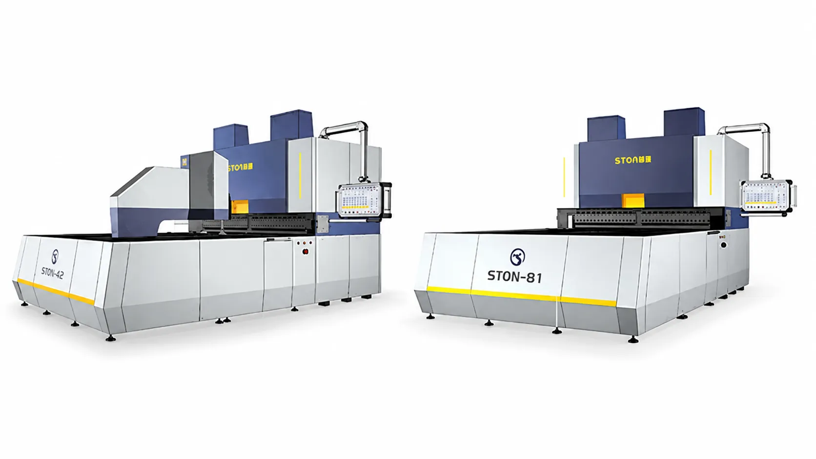
The bending module is selected by frame size, not by a single universal model. STON’s press-arm panel benders run from the A (1000) frame up to the D+ (2800) frame, each available in welded or cast-body construction, with the cast-body option rated for thicker material at full bend.
| Cadre | Max. Bending Size (mm) | Max. Thickness at Full Bend | Bending Height Options (mm) | Servo Axes |
|---|---|---|---|---|
| A (1000) Welding | 1000 × 1000 | CR 1.5 mm / SS 1.0 mm | 170 / 300 / 400 | 15 |
| A+ (1200) Welding | 1200 × 1200 | CR 1.5 mm / SS 1.0 mm | 170 / 300 / 400 | 15 |
| B (1400) Welding | 1400 × 1250 | CR 1.5 mm / SS 1.0 mm | 170 / 300 / 400 | 15 |
| B (1400) Casting | 1400 × 1250 | CR 2.0 mm / SS 1.2 mm | 170 / 300 / 400 | 15 |
| B+ (1600) Casting | 1600 × 1250 | CR 2.0 mm / SS 1.2 mm | 170 / 300 / 400 | 15 |
| C (2000) Casting | 2000 × 1500 | CR 2.0 mm / SS 1.2 mm | 170 / 300 / 400 | 15 |
| D (2500) Casting | 2500 × 1500 | CR 2.0 mm / SS 1.2 mm | 170 / 300 / 400 | 15 |
| D+ (2800) Casting | 2800 × 1500 | CR 2.0 mm / SS 1.2 mm | 170 / 300 / 400 | 15 |
For enclosure work, frame selection maps roughly to cabinet width: filing-cabinet and small enclosure doors typically fit the A or A+ frame, standard distribution cabinet panels fall in the B to C range, and wide switchgear or floor-standing communication cabinet panels push toward the D or D+ frame. All frames in this series share a 15-axis servo configuration and support optional auxiliary knives and automatic tool change for mixed panel geometry — the frame size, not the control system, is what changes as panels get larger.
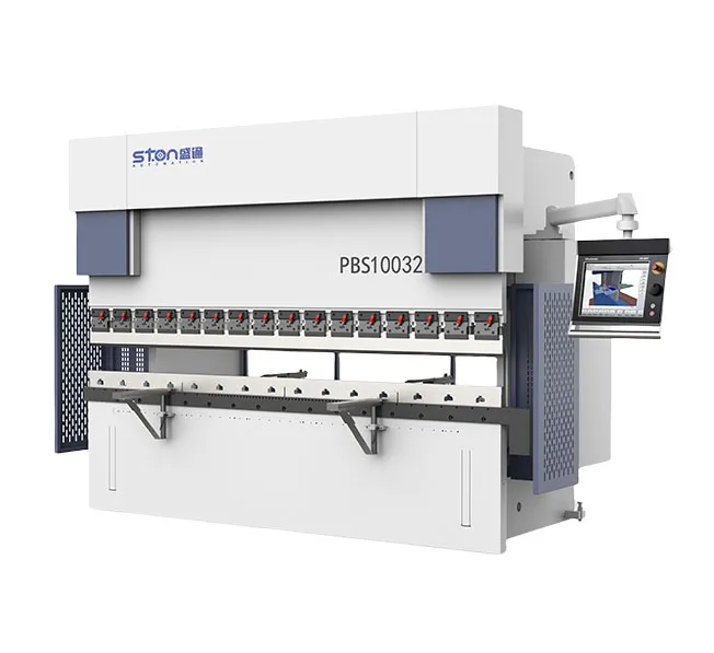
Turret punching and laser cutting solve different parts of the same problem, and an enclosure line often uses both in sequence rather than choosing one over the other.
STON’s mechanical turret punch runs a 30 rpm turret speed at ±0.1 mm machining accuracy with a 150 kg load capacity, drawing roughly 2 kW; the servo turret punch raises turret speed to 40 rpm at the same ±0.1 mm accuracy and 150 kg capacity, drawing 3–5 kW. Both are suited to repetitive hole patterns, louvers, and forming operations where the same tool strikes the same feature hundreds of times per panel — mounting-hole grids on a communication cabinet chassis are a typical case.
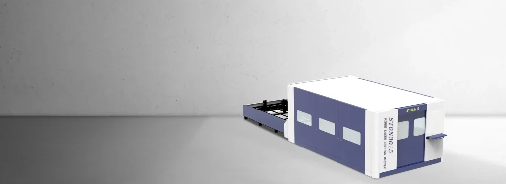
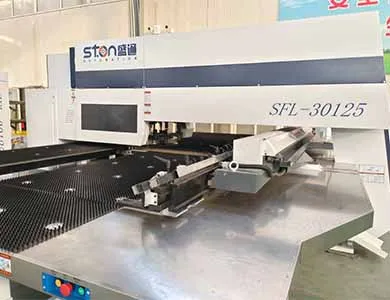
Laser cutting earns its place where the cutout geometry is irregular, curved, or changes frequently between product variants, since there is no tooling to swap between designs. STON’s laser cutting stage handles carbon steel, stainless steel, galvanized sheet, and aluminum, and pairs with coil feeding, stacking, and robot loading in the integrated line. Where a lower-volume shop needs both processes but doesn’t need a full coil line, STON’s SFL series punch-laser combined machine performs both operations on a single sheet-fed station instead — worth noting as a distinct product from the coil-fed line covered here, not a substitute module within it.
Floor space is usually the first constraint that forces a configuration change, and it is worth working through before requesting a formal layout. STON’s laser cutting units alone range from roughly 4,500 mm × 2,600 mm (single-table 3015) up to 16,000 mm × 4,100 mm (dual-table 6025) — before adding the uncoiler, leveler, punching cell, bending cell, and loading buffer that sit around them.
STON’s laser units require a three-phase 380V/50Hz supply; models up to the 4020 size recommend a 60 kVA supply, while the higher-power 6020/6025 tier recommends 120 kVA. Confirm your facility’s available electrical capacity against this before finalizing model selection — it is a common point where a floor-space-only layout review misses a real constraint.
Published specifications give you speed, not a throughput number, and the two are not the same thing. STON’s line speed is stated as 0–12 m/min adjustable, with a 5 m/min threading speed for material setup.
Author estimate, not a verified customer figure: for a mid-size distribution cabinet door panel roughly 600 mm long along the feed direction, running the line at a conservative 6 m/min average (accounting for punching and bending cycle time rather than pure line speed), a single-shift 8-hour window with two hours reserved for changeovers, material loading, and normal stoppages works out to a rough planning range of 250–400 finished panels per shift. This figure assumes one panel geometry running continuously; mixed-product runs with frequent tool or program changes will fall well below that range.
Treat this range as a starting point for capacity planning, not a quoted commitment — actual output depends on your specific panel geometry, hole count, bend count, and how much of the cycle time sits in punching versus bending. Ask STON‘s team to model the figure against your part drawing before using it in an internal business case.
The coil-fed line adds uncoiling and leveling upstream and runs laser cutting, punching, and bending under one control system with automatic material handling between stages. A standalone panel bender and turret punch press are typically fed with pre-cut sheet stock and run as independent stations, each with its own setup and handling.
Yes, within the published thickness limit of 1.5 mm for stainless steel, versus 2.0 mm for cold-rolled and galvanized sheet on the same line.
The largest cataloged panel bender frame (D+) handles up to 2,800×1,500 mm at full bend on cast-body construction. STON’s company-level material separately references bending lengths up to 4,100 mm; this figure is not yet confirmed against a specific frame and should be verified with STON engineering before it’s used in a quote.
Sources disagree. STON’s company materials state ±0.01 mm angle/dimension accuracy for the panel bender series, while the verified official website states ±0.05 mm assembly accuracy across STON’s manufacturing process generally. This article uses the ±0.05 mm figure as the more conservative, site-verified value; treat ±0.01 mm as unconfirmed until STON engineering clarifies which figure applies to which measurement
Three configurations: a robotic arm unit, a gantry system, and a truss-type manipulator. Selection depends on panel size and plant layout rather than one option being universally faster.
Not necessarily. Under the EU Machinery Directive 2006/42/EC and its successor Regulation (EU) 2023/1230, an assembly of machines under a shared control system is generally assessed as a single piece of machinery in its own right, which can require a combined risk assessment beyond each module’s individual certification. Confirm the applicable scope with your integrator.

Que vous modernisiez une ligne existante ou que vous lanciez un nouveau projet, STON personnalisera une solution CNC pour votre production.


