Somos responsables de la construcción-----somos responsables de la fabricación-----somos responsables de la formación

En Línea de Producción Automática de Chapa Metálica conecta desenrollado, nivelado, corte, punzonado, formado y manipulación de piezas bajo un sistema de control unificado, de modo que el material pasa de bobina a panel terminado sin transferencia manual. Lo que decide si funciona no son las máquinas individuales. Es la sincronización de takt, el dimensionamiento de buffers y la disponibilidad combinada de la línea.
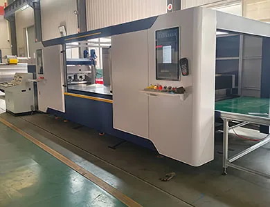
“Línea automática” se usa para cuatro cosas diferentes en este mercado. Los compradores reciben cotizaciones de Nivel 2 y presupuestan para Nivel 4, o viceversa. La distinción siguiente es la que uso en análisis preventa, y se correlaciona directamente con cuánto gastas en software de control en lugar de acero.
| Nivel | Configuración | Transferencia de material | Capa de control | Operadores por turno (estimación del autor) |
| L0 — Islas de máquinas | Standalone laser, turret punch, press brake | Forklift, trolley, hand | Each machine programmed separately | 1 per machine |
| L1 — Automated cell | One machine plus robot or truss loader | Automatic at that machine only | Machine CNC plus handling PLC | 1 supervising 2–3 cells |
| L2 — Linked cells | Two or more cells joined by conveyor or transfer unit, with buffers | Automatic between linked stations | Cell-level handshake signals | 1–2 for the linked group |
| L3 — Coil-fed integrated line | Uncoiling, levelling, blanking, punching, bending, stacking in sequence | Automatic end to end | Unified line control with scheduling and data traceability | 1–2 monitoring, plus coil loading |
STON’s integrated lines sit at L2 and L3, and the line control layer is specified as a unified system supporting process interconnection, intelligent scheduling and data traceability across the whole line. That last item, traceability, is what separates a line from a row of machines that happen to be bolted together: without part-level data passing between stations, you cannot diagnose where a dimensional drift started.
Most factories that ask me for a full line need L1 or L2. That is not a smaller sale. It is a shorter payback.
A coil-fed line starts with the two stations that determine everything downstream. If the blank leaves the leveller with residual stress or out-of-tolerance flatness, the laser will cut it accurately and the panel bender will bend it accurately, and the finished cabinet door will still be twisted.
The uncoiler unwinds the strip and holds a synchronous material balance with the leveller, which is the first synchronisation point on the line. STON’s uncoiler body and base are welded structures given heat ageing treatment. On the levelling side, roller material is specified as 40Cr, with work-roller bearings that are self-aligning or needle roller types, and the levelling stack itself is configured to the customer’s thickness and flatness requirement rather than supplied as one fixed build.
Published accuracy for the coil-fed line:
| Parámetro | Published value |
| Precisión de nivelación | ±1 mm/m² |
| Precisión diagonal | ≤1 mm per 2000 mm |
| Calidad de superficie | Strip surface flat, no processing defects introduced |
| Velocidad de enhebrado | 5 m/min |
| Leveller line speed | 0–12 m/min, ajustable |
| Working height | +800 mm |
Two things to check against your own parts. First, ±1 mm/m² is a line-level flatness figure, not a part flatness guarantee after forming. Second, the +800 mm working height fixes the elevation of everything you connect downstream, including any existing machine you plan to integrate.
This is where most line configurations are decided, and where the honest answer depends on your hole population rather than on which technology is more modern.
| Dimensión | Coil-fed laser blanking | CNC turret punching | Punch–laser combined |
|---|---|---|---|
| El más adecuado | Complex contours, varied outlines, low hole count | Repeating hole patterns, louvres, forming, ribs | Mixed parts where both contour and forming are needed on the same panel |
| Herramientas | None for contour changes | Turret tools required per feature | Turret plus laser head |
| Forming features (louvre, rib, emboss, countersink) | Not possible | Yes | Yes |
| Programme change cost | Software only | Software plus tool availability | Software plus tool availability |
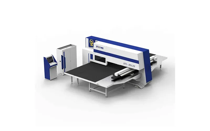
| STON reference | Fiber laser cutting system, multiple power options | SF servo series, JT mechanical series | SFL series |
| Space | Line footprint driven by coil length | 5200 × 5000/5500 mm class footprint (JT) | Roughly 40% less floor area than separate punch plus laser, per STON documentation |
Published turret punch parameters, both series:
| Parámetro | SF servo series | JT mechanical series |
| Velocidad máxima de la torreta | 40 rpm | 30 rpm |
| Machining accuracy | ±0,1 mm | ±0,1 mm |
| Maximum load capacity | 150 kg | 150 kg |
| Combined power consumption | Aprox. 3–5 kW | ≤2 kW |
| Air source pressure | 0,55 MPa | 0,55 MPa |
| Alimentación | 380 V ±5% | 380 V ±5% |
| External dimensions (X/Y/H) | 5200 × 5000/5500/6500 × 2230 mm | 5200 × 5000/5500 × 2100 mm |
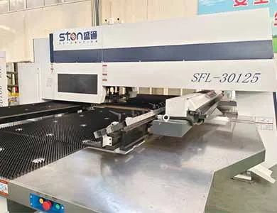
The SFL punch–laser machine is published at 300/400 kN (30/40 T) punching force in an O-type closed frame, with X-axis capacity of 2500 mm in one position and up to 5000 mm using secondary positioning, Y-axis 1250/1500 mm, and a turret layout of 16A, 11B, 3C, 2D stations including one 1B and one 1C rotary station. One CNC system controls punch, laser and axis motion together, so the part is programmed once.
The common misconception here: buyers compare laser cutting speed against punching speed on a single feature and conclude laser wins. On a 1.0 mm cabinet panel with 180 identical vent slots, a single turret hit per slot at 30–40 rpm turret indexing will finish the panel while the laser is still tracing perimeters, and the punch also forms the louvre in the same operation. Count features by type before you compare.
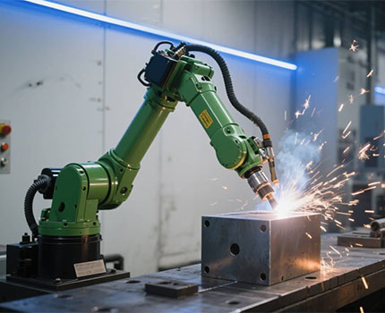
The welding workstation is a robot, positioner, tooling fixtures and a seam tracking system, covering butt, fillet and spot welding. Two planning notes that matter more than the robot brand.
Fixture cost is usually underestimated. A welding cell that handles six cabinet variants needs fixtures for six variants, and fixture lead time frequently exceeds machine lead time. Second, welding introduces distortion, which means your dimensional tolerance stack has to be allocated across forming and welding together rather than assigned entirely to the forming station.
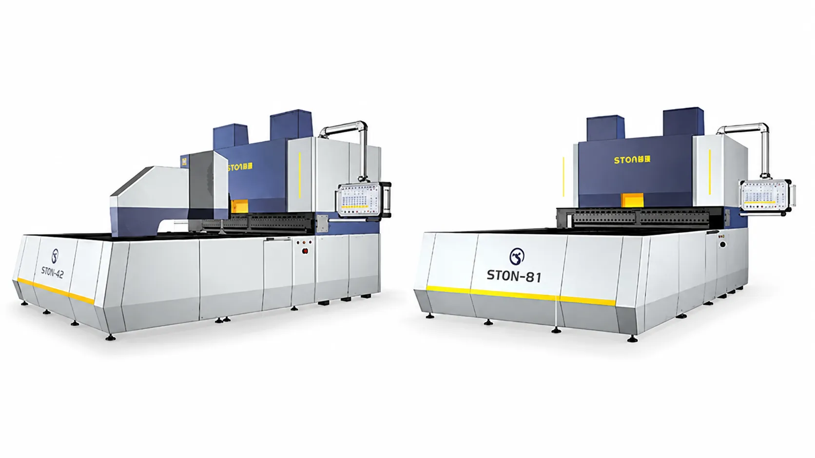
Material handling between stations uses robotic arms, truss manipulators or gantry systems. STON’s panel benders y press brakes are published with a native loading and unloading interface stated as compatible with most robotic arm and gantry brands on the market, which matters if you already run a specific robot fleet and want programming consistency.
Here is the part competitors’ process guides skip. A line is a set of stations with different natural cycle times, joined by transfer devices, and it produces at the rate of its slowest element minus the losses caused by every stoppage upstream and downstream of that element.
Three mechanisms manage this.
Takt matching. Each station’s cycle time is measured for your actual worst-case part, not the demonstration part. The line takt is the longest station cycle. Stations faster than takt idle, which is fine and normal; a line where every station is fully loaded has no capacity to recover from a stoppage.
Buffers. Between stations, a buffer decouples them so a short stop at one station does not starve or block its neighbour. Buffer sizing is arithmetic, not judgement:
Minimum buffer parts = upstream throughput rate × expected stoppage duration
At 65 parts/hour upstream and a six-minute typical clearance for a jam or tool change, that is 65 × 0.1 = 6.5, so seven part positions. Halve the buffer and you have roughly halved the protection.
Handshake and scheduling. The line control system decomposes an order into station-level tasks, releases them in sequence, and holds a station until its downstream neighbour confirms readiness. STON specifies a unified control system across the customised line with process interconnection and data traceability, which is the layer that carries these confirmations.
Ordered, because doing these out of sequence is the most common cause of a line that runs for three weeks and then produces scrap:
STON does not publish list prices for integrated lines; configuration drives the figure, so pricing is by enquiry. The variables that move it most are laser power (published 1–6 kW), the number of stations, the forming bed choice between casting and welded, robot or truss handling, welding fixture count, and the depth of the line control and traceability software.
A quotation you can actually evaluate contains, per station: the cycle time for your named part, the stated availability assumption, buffer positions and capacity, the utility load, the physical footprint including maintenance access, and the acceptance criteria with tolerances. If those six items are absent, you are comparing prices for machines whose combined output nobody has committed to.
The next step that saves the most money is unglamorous: send part drawings, material grades, thickness range, annual volumes per part number and current batch sizes, then ask for the bottleneck analysis before asking for a price. If a supplier can produce a line layout without ever seeing your batch sizes, the layout is generic.
For factories running a first automation project, one open question worth resolving early is where your part data will live. A line with traceability produces data per part; if there is no receiving system for it on your side, you have bought a capability you will not use in year one.
Q: What is the difference between a sheet metal automatic production line and a set of automated machines?
A: A line has a control layer above the machines that sequences tasks, holds handshakes between stations, and passes part data along the process. Automated machines each run their own programme and rely on operators or transport to move work between them. The machines can be identical; the software and buffer design are not.
Q: What materials and thicknesses can a coil-fed line process?
A: STON’s published range is cold-rolled sheet, galvanised sheet and stainless steel at 0.5–2.0 mm, with coil weight up to 10 T, coil inner diameter φ508–630 mm and outer diameter φ1000–1600 mm.[^3] Company overview documentation states stainless steel at ≤1.5 mm; confirm the limit for your grade before ordering.
Q: How many operators does an integrated line need?
A: In my experience it is one to two people per shift for monitoring, plus coil loading and finished-part removal, though the number depends on how much of the sorting and stacking is automated. Treat any single-number claim, including that one, as configuration-dependent rather than a specification.
Q: Can I integrate an automatic line with machines I already own?
A: Sometimes. The practical constraints are working height, which is +800 mm on the coil-fed line, whether your existing machine’s CNC exposes the input and output signals needed for handshaking, and whether its cycle time fits the line takt. An existing machine that becomes the bottleneck removes most of the benefit of integrating it.
Q: What is a realistic availability figure to plan around?
A: Plan with station-level availability from your own maintenance records, then multiply across coupled stations rather than averaging. For coupled stations at 95% each, five stations calculate to about 77%. Buffers raise the real figure; the calculation gives you the floor to design against.
Q: Should the line use laser blanking, turret punching, or both?
A: Count the features on your highest-volume parts. Repeating holes, louvres, ribs and embossing favour turret punching, since forming features cannot be produced by a laser. Varied contours with few holes favour laser. Mixed populations on the same panel are the case for a punch–laser combined machine, published by STON as occupying roughly 40% less floor area than separate machines.
Q: How long does commissioning take?
A: It depends on station count and how much of the part programming exists beforehand, so I will not give you a week count. What I can say is which activity dominates: proving cycle time and first-pass yield on your real parts, not mechanical installation. Build the acceptance protocol around measured yield on a defined batch, and the schedule becomes predictable.
Q: What does an automatic sheet metal production line cost?
A: STON publishes no price range for integrated lines, so this is a quotation item. Cost scales with laser power, station count, handling method, welding fixture count and control software depth. Ask for pricing broken out per station rather than as a single line figure, so you can evaluate which stations actually earn their place.

Tanto si está actualizando una línea existente como si está iniciando un nuevo proyecto, STON personalizará una solución CNC para su producción.


