Siamo responsabili della costruzione----- siamo responsabili della produzione----- siamo responsabili della formazione
La pressa piegatrice idraulica è una macchina di formatura utilizzata per piegare le lamiere in angoli e profili precisi attraverso una forza idraulica controllata. È ampiamente applicata nella produzione industriale di lamiere, dove è richiesta un'elevata precisione di piegatura, una pressione di formatura stabile e risultati ripetibili. Progettate per le officine di produzione e gli ambienti di produzione OEM, le presse piegatrici idrauliche forniscono prestazioni di piegatura affidabili per un'ampia gamma di materiali metallici e spessori. Il sistema idraulico assicura una distribuzione uniforme della forza durante le operazioni di piegatura, aiutando i produttori a mantenere una qualità di formatura costante durante i cicli di produzione continui.

| No. | Nome | 63/1500 | 63/2100 | 63/2550 | 100/3200 | 100/4100 | 150/3200 | 150/4100 | 220/3200 | 220/4100 | 250/3200 | 250/4100 | 320/3200 | 320/4100 | Unità | |
| 1 | Pressione nominale | 630 | 630 | 630 | 1000 | 1000 | 1500 | 1500 | 2200 | 2200 | 2500 | 2500 | 3200 | 3200 | KN | |
| 2 | Lunghezza di curvatura | 1500 | 2100 | 2550 | 3200 | 4100 | 3200 | 4100 | 3200 | 4100 | 3200 | 4100 | 3200 | 4100 | MM | |
| 3 | Distanza tra le colonne | 1200 | 1600 | 2050 | 2700 | 3600 | 2700 | 3600 | 2700 | 3600 | 2700 | 3600 | 2700 | 3600 | MM | |
| 4 | Corsa del cilindro | 215 | 215 | 215 | 215 | 215 | 215 | 215 | 215 | 215 | 225 | 225 | 315 | 315 | MM | |
| 5 | Altezza di apertura | 580 | 580 | 580 | 580 | 580 | 580 | 580 | 580 | 580 | 580 | 580 | 680 | 680 | MM | |
| 6 | Profondità della gola | 350 | 350 | 350 | 390 | 390 | 405 | 405 | 405 | 405 | 405 | 405 | 405 | 405 | MM | |
| 7 | Velocità di movimento del cursore | Scendere rapidamente | 185 | 185 | 185 | 220 | 220 | 180 | 180 | 160 | 160 | 150 | 150 | 130 | 130 | MM/S |
| 8 | Stato di avanzamento dei lavori | 19 | 19 | 19 | 17 | 17 | 14 | 14 | 12 | 12 | 10 | 10 | 9.5 | 9.5 | MM/S | |
| 9 | Ritorno | 180 | 180 | 180 | 210 | 180 | 180 | 170 | 160 | 150 | 150 | 140 | 120 | 110 | MM/S | |
| 10 | Corsa dell'asse X | 500 | 500 | 500 | 500 | 500 | 500 | 500 | 500 | 500 | 500 | 500 | 500 | 500 | 500 | |
| 11 | Corsa dell'asse R | 200 | 200 | 200 | 200 | 200 | 200 | 200 | 200 | 200 | 200 | 200 | 200 | 200 | 200 | |
| 12 | Velocità asse X | 400 | 400 | 400 | 400 | 400 | 400 | 400 | 400 | 400 | 400 | 400 | 400 | 400 | 400 | |
| 13 | Velocità dell'asse R | 200 | 200 | 200 | 200 | 200 | 200 | 200 | 200 | 200 | 200 | 200 | 200 | 200 | 200 | |
| 14 | Potenza del motore principale | 8.7 | 8.7 | 8.7 | 10.8 | 10.8 | 13.2 | 13.2 | 16.7 | 16.7 | 16.7 | 16.7 | 22 | 22 | KW | |
| 15 | Volume dell'olio idraulico | 130 | 180 | 200 | 300 | 400 | 300 | 400 | 300 | 400 | 300 | 400 | 400 | 500 | L | |
| 16 | Dimensioni (L*M*H) | 2000/1620/2470 | 2600/1620/2470 | 3150/1620/2470 | 3720/1720/2550 | 4620/1720/2550 | 3780/1730/2600 | 4680/1730/2600 | 3830/1800/2670 | 4730/1800/2670 | 3830/1800/2670 | 4730/1800/2670 | 3880/2100/3250 | 4760/2100/3250 | MM | |
| 17 | Spessore della macchina utensile (piastra verticale, slitta, piano di lavoro) | 40/50/60 | 40/50/60 | 40/50/60 | 50/60/80 | 50/70/90 | 60/70/90 | 60/80/100 | 70/80/100 | 70/90/110 | 70/80/100 | 70/90/110 | 80/90/110 | 80/100/120 | MM | |
| 18 | Alesaggio del cilindro | 115 | 115 | 115 | 150 | 150 | 180 | 180 | 220 | 220 | 230 | 230 | 270 | 270 | MM | |
| 19 | Diametro dell'asta del cilindro | 110 | 110 | 110 | 145 | 145 | 173 | 173 | 210 | 210 | 220 | 220 | 260 | 260 | MM | |
| 20 | Peso della macchina | 4500 | 5000 | 6000 | 8500 | 10500 | 9200 | 11600 | 11000 | 13200 | 11000 | 13200 | 16800 | 19000 | kg | |
| 21 | Flusso della pompa dell'olio | 16 | 16 | 16 | 20 | 20 | 25 | 25 | 32 | 32 | 32 | 32 | 40 | 40 | L | |
Hydraulic press brakes are engineered to maintain forming accuracy under high load conditions. Structural rigidity and precise hydraulic control work together to deliver stable bending results during long term operation.
Lavorazione di precisione
Flusso automatizzato

Configurazione flessibile
Key Features
Hydraulic systems provide stable and adjustable force suitable for bending thick and high strength metal sheets.

Controlled hydraulic pressure enables precise angle control and repeatable bending accuracy.
Suitable for carbon steel stainless steel aluminum and other common sheet metal materials.
Hydraulic motion ensures smooth forming without sudden impact reducing material stress.
Designed for long term operation in demanding manufacturing environments.
Supports different bending lengths tooling setups and product configurations.
Consistent bending quality is critical for ensuring proper fit and assembly of fabricated metal parts. Inaccurate hydraulic control or unstable machine structure can result in angle deviation surface defects and increased rework. Our hydraulic press brakes are designed to deliver stable bending performance throughout the production cycle. Controlled forming pressure consistent angle accuracy and smooth motion help manufacturers improve overall production efficiency and ensure reliable downstream assembly and welding processes.
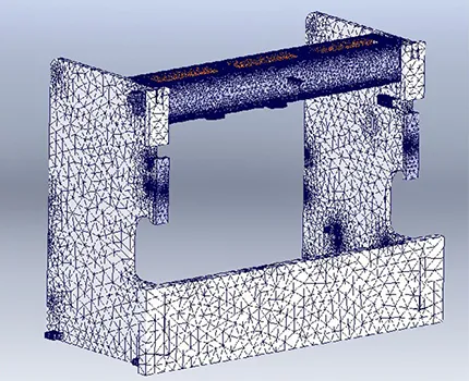
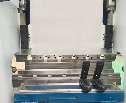
A hydraulic press brake operates through the coordinated interaction of multiple mechanical hydraulic and control systems. Reliable bending performance depends not only on hydraulic power but also on machine structure motion control tooling accuracy and system coordination.
Each hydraulic press brake is engineered as a complete forming system where the hydraulic circuit frame structure drive units and CNC control platform work together. This system based design ensures stable forming accuracy consistent force distribution and long service life under continuous industrial use.
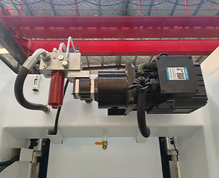
Provides rigidity to withstand high bending force and maintain structural stability.
Generates controlled pressure to support smooth and accurate bending operations.
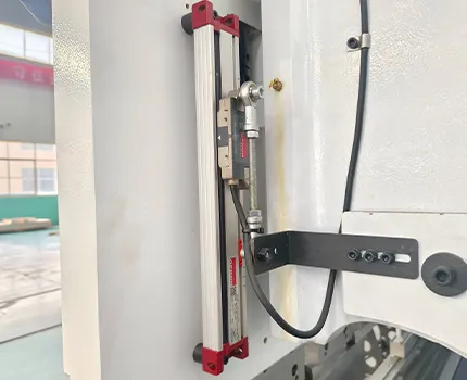
Controls bending speed and positioning accuracy throughout the forming process.

Supports operator safety and stable machine operation during high force forming.
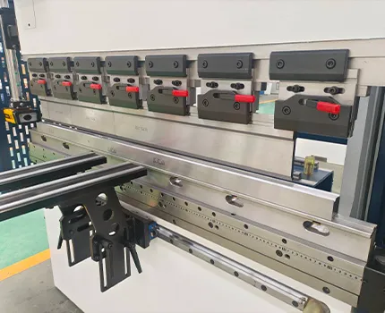
Controls ram movement and positioning accuracy during bending cycles.
Manages bending parameters angle control and repeatable production execution.
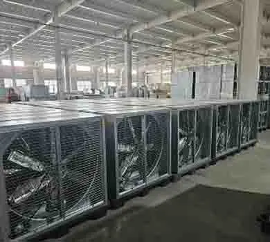
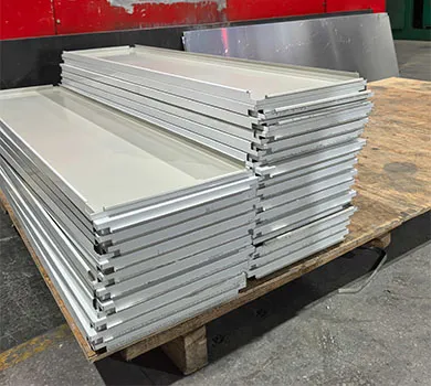
Crediamo nella costruzione di relazioni forti e trasparenti con i nostri clienti. Per questo invitiamo i nostri partner a visitare il nostro stabilimento di produzione all'avanguardia e a vedere da vicino il nostro processo produttivo.
 Antonio
Responsabile acquisti, HVAC
Fabbrica di componenti (Germania)
 Jeffrey
Proprietario della fabbrica, utensili da cucina inossidabili
Produttore (USA)
 Jared
Jared- Direttore delle operazioni, Cabinet elettrico
Fabbrica (Canada)
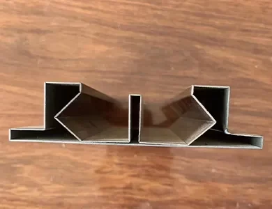
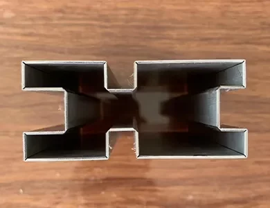
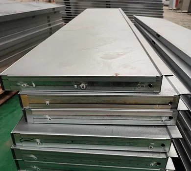
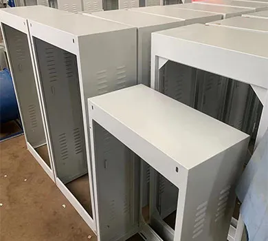
A hydraulic press brake is used to bend sheet metal into specific angles and shapes by applying controlled hydraulic force. It is commonly used in industrial fabrication for cabinets enclosures frames and structural components.
Hydraulic press brakes use fluid pressure to generate bending force which provides smooth motion and stable force control. This makes them suitable for bending thicker materials and maintaining consistent forming accuracy.
Hydraulic press brakes can process carbon steel stainless steel aluminum and other metal sheets. Bending parameters are adjusted based on material thickness strength and bending requirements.
Accuracy is maintained through precise hydraulic pressure control rigid machine structure accurate tooling and CNC controlled positioning which together ensure repeatable bending results.
Yes hydraulic press brakes are designed for long term industrial use. Stable hydraulic systems durable components and proper maintenance allow reliable continuous operation in manufacturing environments.

Sia che stiate aggiornando una linea esistente o iniziando un nuovo progetto, STON personalizzerà una soluzione CNC per la vostra produzione.


