We're responsible for building-----we're responsible for manufacturing-----we're responsible for training

A filing cabinet body and drawer front can go from flat coil steel to a bent, punched shell in one continuous automated sequence — uncoiling, leveling, laser cutting, punching, and bending — without the part being set down and re-picked between stations, which is where most consistency loss happens on manual lines.
Most equipment pages describe a production line station by station, as if each machine operates in isolation. That’s not how a filing cabinet body actually experiences the line. The same steel strip that gets uncoiled at 8:00 AM is the same blank that gets laser-cut ten minutes later, and the same blank is the panel that gets punched with lock-body holes and vent louvers before it reaches the bending station. Every handoff between those stages is a place where a manual shop introduces variation — a part set down slightly off-square, a stack that gets reshuffled, an operator who eyeballs an edge instead of measuring it.
This walkthrough follows a single filing cabinet body panel and a drawer front through STON’s coil-fed automated line, stage by stage, and flags where each stage either removes or still depends on a manual checkpoint.

The steel coil — cold-rolled, galvanized, or stainless, in the 1000–1500 mm width range this line class handles — loads onto the uncoiler, which unwinds the strip and feeds it into the leveler in sync with the leveling rollers. The uncoiler and leveler frame are welded structures that go through heat-aging treatment before assembly, which matters here specifically because an unstressed leveler bed is what keeps the leveling accuracy consistent as thousands of feet of strip pass through it, not just at startup.
Rated leveling accuracy for this line class is ±1 mm/m², with diagonal accuracy held to ≤1 mm across a 2000 mm span. Threading speed is 5 m/min; once threaded, the line runs at an adjustable 0–12 m/min. For a filing cabinet body panel — typically in the 400–600 mm width range — this means the strip is flat enough entering the cutting stage that the panel bender downstream isn’t asked to compensate for a wave the leveler should have removed.
Manual-line comparison: on a shop that hand-feeds pre-cut blanks from a shear, flatness depends on how the blank was stacked and how long it sat under its own weight. A coil-fed leveler removes that variable at the source, before the blank exists as a discrete part.
Once leveled, the strip feeds directly into the laser cutting head — fiber laser, 1–6 kW depending on the configured line, with 3 kW and 6 kW as the two most commonly specified powers for this material range. For filing cabinet steel (typically 0.5–1.5 mm cold-rolled or galvanized), cut quality at this power range should produce burr-free edges without a secondary deburring pass.
This is also where the body panel and the drawer front get nested together on the same sheet. Nesting software lays out both parts — the larger body panel and the smaller drawer blank — to minimize scrap on the same strip pass, rather than running them as two separate cutting jobs on two separate material setups.
Edge case to plan for: stainless steel filing cabinets (common for lab and medical furniture applications) cap out at 1.5 mm on this coil-fed line, versus 2.0 mm for cold-rolled steel. If your product spec calls for 2 mm stainless — not common for filing cabinets, but it happens on reinforced fire-rated bodies — that thickness needs to be confirmed against the specific laser configuration before the line is quoted, not assumed from the cold-rolled figure.

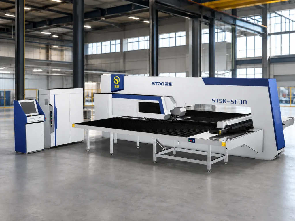
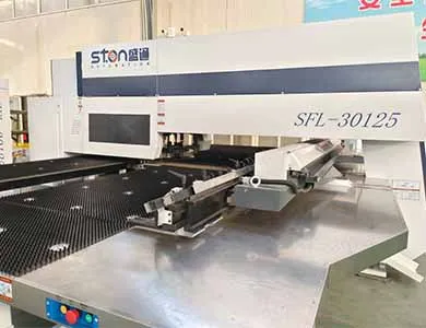
The cut blank moves to the CNC turret punch press for the features a laser alone won’t produce efficiently: louvered vents, embossed ribs for panel stiffness, and forming operations like trimming and rib pressing. On the servo turret configuration, machining accuracy is rated at ±0.1 mm, with a maximum turret speed of 40 rpm and a 150 kg load capacity on the worktable — more load capacity than a single filing cabinet body panel will ever use, but relevant if the line is later shared across heavier enclosure products.
Automatic loading, sheet separation, positioning, unloading, and stacking are unmanned through this stage. That’s the specific claim worth being precise about: it means the punch press’s material handling doesn’t require an operator between cycles, not that the whole line runs with zero human oversight anywhere.
Where manual shops lose here: hole position on a filing cabinet lock body is unforgiving — a lock mechanism that’s off by even 0.3 mm can bind. On a manual turret or a hand-fed punch, that tolerance depends on how consistently the operator re-registers the part after the laser-cutting stage. On the integrated line, the part never leaves the automated handling chain between cutting and punching, so the registration reference doesn’t change hands.

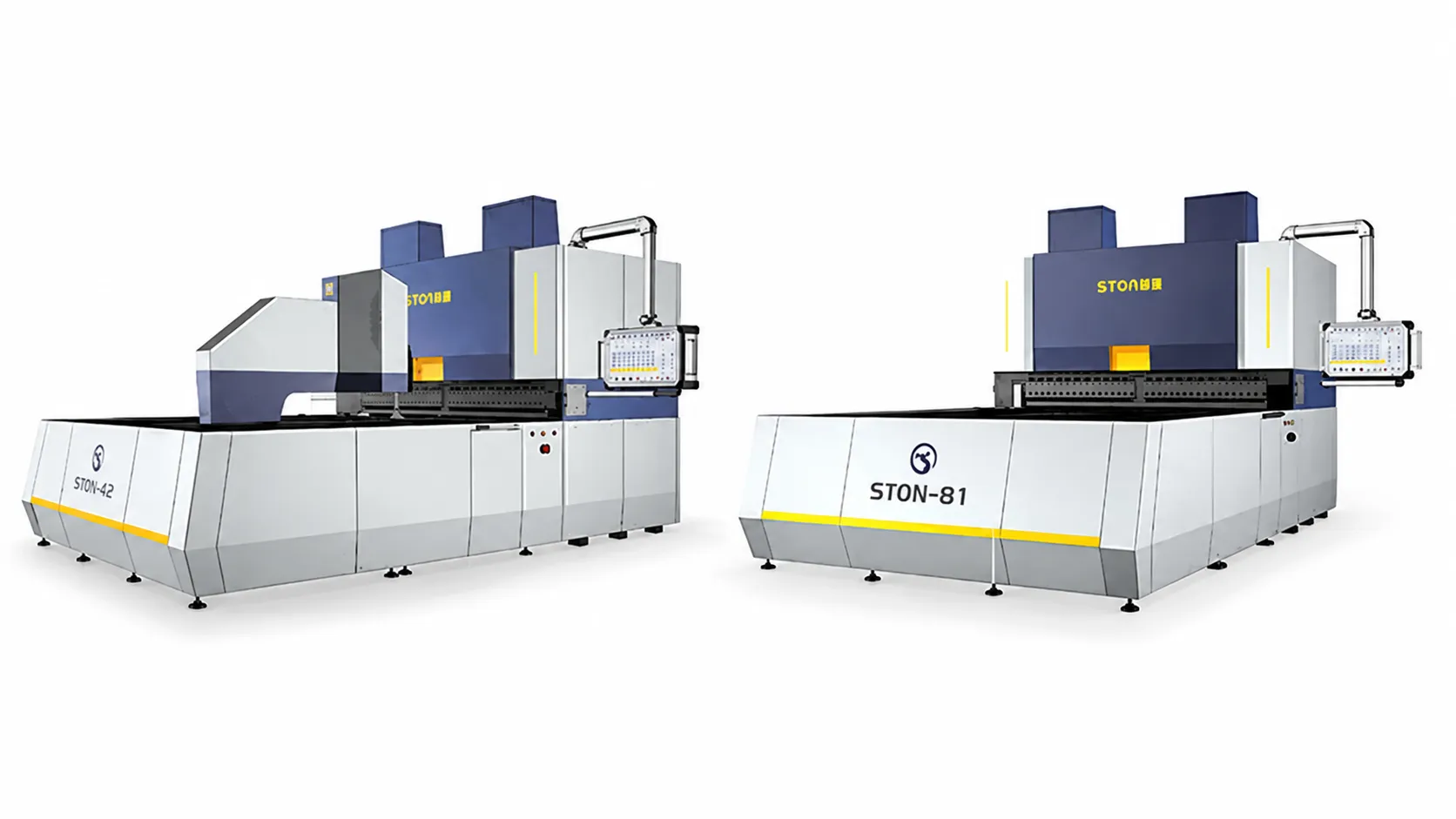
The punched blank reaches the panel bender last. For filing cabinet body dimensions (commonly in the 1200–2000 mm range for full-height bodies, smaller for drawer fronts), the relevant panel bender frame sizes are:
| Model | Max Bending Size (mm) | Max Bending Height (mm) | Max Thickness at Full Bend | Servo Axes |
|---|---|---|---|---|
| B (1400) | 1400 × 1250 | 170 / 300 / 400 | CR 1.5 mm / SS 1.0 mm (welded) | 15 |
| B+ (1600) | 1600 × 1250 | 170 / 300 / 400 | CR 1.5 mm / SS 1.0 mm (welded) | 15 |
| C (2000) | 2000 × 1500 | 170 / 300 / 400 | CR 1.5 mm / SS 1.0 mm (welded) | 15 |
Cast-body versions of the same frame sizes handle up to CR 2.0 mm / SS 1.2 mm at full bend — a real difference in what the machine can form, not a cosmetic spec, so the welded-vs-cast choice should be made against your heaviest-gauge body panel, not your average one.
Published assembly accuracy for STON equipment is ±0.05 mm, per current manufacturer specifications. The bending sequence itself is where a filing cabinet body’s squareness gets decided: the panel bender’s compensation adjustment system lets bending accuracy and angle be corrected at any point along the fold line without physical shims, which is what keeps a four-sided body panel — folded on two or four edges depending on design — square enough that the drawer slides in without racking.
Automatic loading and unloading integration: the panel bender retains a docking interface that pairs with robotic arm, gantry, or truss-type loading and unloading systems. For a filing cabinet line running body panels and drawer fronts back to back, this is what keeps the bender fed without an operator physically placing each blank — the same unmanned-handling principle carried through from the punching stage.
The stages above cover uncoiling through bending. What they don’t cover, on a standard filing cabinet body, is corner welding and final assembly — joining the bent panel’s seams, mounting slides, and attaching hardware. STON’s line documentation lists automated welding as a separate workstation (robot, positioner, tooling fixture, and seam-tracking system) that can be added to a line, but it’s a distinct integration decision, not a default inclusion, and it needs to be scoped against your specific body design before it’s assumed to be part of the quote.
Yes — the laser cutting stage nests both part types on the same coil pass, and both feed through the same punching and bending stations sequentially.
0.5–2.0 mm for cold-rolled and galvanized steel; stainless steel is capped at 1.5 mm on the standard coil-fed laser configuration.
Not when paired with automatic loading and unloading (robotic arm, gantry, or truss). Without that pairing, the bender still requires manual load/unload between cycles.
The cast-frame version forms up to CR 2.0 mm / SS 1.2 mm at full bend versus CR 1.5 mm / SS 1.0 mm for the welded frame — relevant if your heaviest body panel gauge is near the welded frame’s ceiling.
No — welding is a separate workstation that can be integrated but isn’t a default line component. It needs to be scoped against your specific body design.
The servo turret punch press is rated at ±0.1 mm machining accuracy.
This line class supports coil weights up to 10T with inner diameters of Ø470–630 mm, but actual run length depends on your specific part’s material usage per unit — this isn’t a figure STON’s published documentation quantifies in cycles-per-coil, so it should be calculated against your part’s blank size.
STON’s line design is customized around the customer’s existing layout, product structure, and process flow rather than sold as a fixed package — this is scoped case by case.

Whether you're upgrading an existing line or starting a new project, STON will customize a CNC solution for your production.


