Siamo responsabili della costruzione----- siamo responsabili della produzione----- siamo responsabili della formazione

Un Linea di produzione automatica per lamiera collega svolgimento, spianatura, taglio, punzonatura, formatura e movimentazione dei pezzi sotto un unico sistema di controllo, in modo che il materiale passi dalla bobina al pannello finito senza trasferimenti manuali. Ciò che determina se il sistema funziona non sono le singole macchine, ma l'allineamento del takt time, il dimensionamento dei buffer e la disponibilità complessiva della linea.
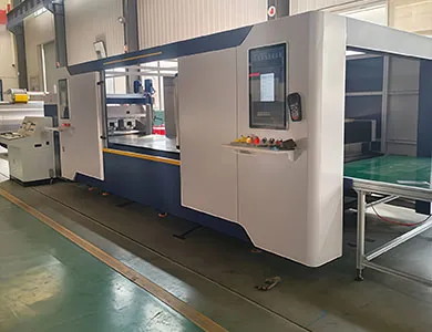
“In questo mercato, l'espressione ”linea automatica" viene utilizzata per indicare quattro cose diverse. Agli acquirenti vengono forniti preventivi di Livello 2 mentre il budget è pensato per il Livello 4, o viceversa. La distinzione riportata di seguito è quella che utilizzo nell'analisi pre-vendita e si riflette direttamente sulla spesa destinata al software di controllo piuttosto che all'acciaio.
| Livello | Configurazione | Trasferimento del materiale | Livello di controllo | Operatori per turno (stima dell'autore) |
| L0 — Isole di macchine | Laser standalone, punzonatrice a torretta, pressa piegatrice | Carrello elevatore, carrello, manuale | Ogni macchina programmata separatamente | 1 per macchina |
| L1 — Cella automatizzata | Una macchina più robot o caricatore a portale | Automatico solo su quella macchina | CNC macchina più PLC di movimentazione | 1 che supervisiona 2–3 celle |
| L2 — Celle collegate | Due o più celle collegate da trasportatore o unità di trasferimento, con buffer | Automatico tra stazioni collegate | Segnali di handshake a livello di cella | 1–2 per il gruppo collegato |
| L3 — Linea integrata alimentata a bobina | Svolgimento, livellamento, tranciatura, punzonatura, piegatura, impilamento in sequenza | Automatico dall'inizio alla fine | Controllo unificato della linea con schedulazione e tracciabilità dei dati | Monitoraggio 1–2, più caricamento bobina |
Le linee integrate STON si collocano ai livelli L2 e L3, e lo strato di controllo della linea è specificato come un sistema unificato che supporta l'interconnessione dei processi, la schedulazione intelligente e la tracciabilità dei dati lungo l'intera linea. Quest'ultimo elemento, la tracciabilità, è ciò che distingue una linea da una fila di macchine che risultano semplicemente imbullonate insieme: senza il passaggio di dati a livello di pezzo tra le stazioni, non è possibile diagnosticare dove ha avuto inizio una deriva dimensionale.
La maggior parte degli stabilimenti che mi chiedono una linea completa ha bisogno di L1 o L2. Non è una vendita di minor valore. È un rientro dell'investimento più rapido.
Una linea alimentata a coil inizia con le due stazioni che determinano tutto ciò che segue. Se il pezzo grezzo esce dalla spianatrice con tensioni residue o una planarità fuori tolleranza, il laser lo taglierà con precisione e la pannellatrice lo piegherà con precisione, ma l'anta finita dell'armadio sarà comunque deformata.
Lo svolgitore svolge il nastro e mantiene un bilanciamento sincronizzato del materiale con la spianatrice, che costituisce il primo punto di sincronizzazione della linea. Il corpo e la base dello svolgitore STON sono strutture saldate sottoposte a trattamento di stabilizzazione termica. Per la spianatura, il materiale dei rulli è specificato come 40Cr, con cuscinetti dei rulli di lavoro del tipo autoallineante o a rullini; inoltre, il gruppo di spianatura è configurato in base ai requisiti del cliente relativi a spessore e planarità, invece di essere fornito in un'unica configurazione fissa.
Precisione dichiarata per la linea alimentata a coil:
| Parametro | Valore dichiarato |
| Precisione di livellamento | ±1 mm/m² |
| Precisione diagonale | ≤1 mm ogni 2000 mm |
| Qualità della superficie | Superficie del nastro piana, senza difetti di lavorazione introdotti |
| Velocità di filettatura | 5 m/min |
| Velocità della linea di raddrizzatura | 0–12 m/min, regolabile |
| Altezza di lavoro | +800 mm |
Due aspetti da verificare rispetto ai propri pezzi. Primo, ±1 mm/m² è un valore di planarità a livello di linea, non una garanzia di planarità del pezzo dopo la formatura. Secondo, l'altezza di lavoro di +800 mm determina l'elevazione di tutto ciò che si collega a valle, compresa qualsiasi macchina esistente che si intende integrare.
È qui che si decide la maggior parte delle configurazioni della linea, e la risposta più onesta dipende dalla distribuzione dei fori, non da quale tecnologia sia più moderna.
| Parametro | Tranciatura laser alimentata da coil | Punzonatura CNC a torretta | Combinata punzonatura-laser |
|---|---|---|---|
| Più adatto per | Contorni complessi, profili variabili, basso numero di fori | Schemi di fori ripetuti, louvre, formatura, nervature | Parti miste in cui sono necessari sia contorni che formatura sullo stesso pannello |
| Attrezzatura | Nessuno per modifiche del contorno | Utensili torretta richiesti per funzione | Torretta più testa laser |
| Funzioni di formatura (louvre, nervatura, imbutitura, svasatura) | Non possibile | Sì | Sì |
| Costo di cambio programma | Software only | Software plus tool availability | Software plus tool availability |
| STON reference | Fiber laser cutting system, multiple power options | SF servo series, JT mechanical series | SFL series |
| Space | Line footprint driven by coil length | 5200 × 5000/5500 mm class footprint (JT) | Roughly 40% less floor area than separate punch plus laser, per STON documentation |
Published turret punch parameters, both series:
| Parametro | SF servo series | JT mechanical series |
| Velocità massima della torretta | 40 giri/min | 30 giri/min |
| Precisione di lavorazione | ±0,1 mm | ±0,1 mm |
| Capacità di carico massima | 150 kg | 150 kg |
| Consumo energetico combinato | Circa 3–5 kW | ≤2 kW |
| Air source pressure | 0,55 MPa | 0,55 MPa |
| Alimentazione elettrica | 380 V ±5% | 380 V ±5% |
| External dimensions (X/Y/H) | 5200 × 5000/5500/6500 × 2230 mm | 5200 × 5000/5500 × 2100 mm |
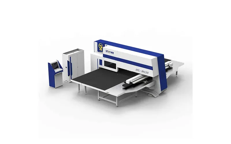
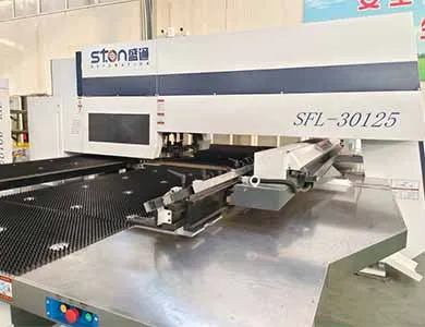
The SFL punch–laser machine is published at 300/400 kN (30/40 T) punching force in an O-type closed frame, with X-axis capacity of 2500 mm in one position and up to 5000 mm using secondary positioning, Y-axis 1250/1500 mm, and a turret layout of 16A, 11B, 3C, 2D stations including one 1B and one 1C rotary station. One CNC system controls punch, laser and axis motion together, so the part is programmed once.
The common misconception here: buyers compare laser cutting speed against punching speed on a single feature and conclude laser wins. On a 1.0 mm cabinet panel with 180 identical vent slots, a single turret hit per slot at 30–40 rpm turret indexing will finish the panel while the laser is still tracing perimeters, and the punch also forms the louvre in the same operation. Count features by type before you compare.
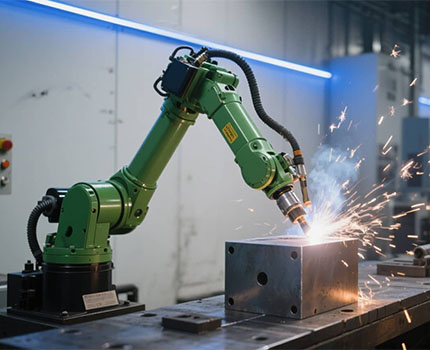
The welding workstation is a robot, positioner, tooling fixtures and a seam tracking system, covering butt, fillet and spot welding. Two planning notes that matter more than the robot brand.
Fixture cost is usually underestimated. A welding cell that handles six cabinet variants needs fixtures for six variants, and fixture lead time frequently exceeds machine lead time. Second, welding introduces distortion, which means your dimensional tolerance stack has to be allocated across forming and welding together rather than assigned entirely to the forming station.
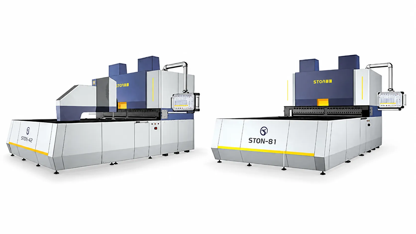
Material handling between stations uses robotic arms, truss manipulators or gantry systems. STON’s panel benders e press brakes are published with a native loading and unloading interface stated as compatible with most robotic arm and gantry brands on the market, which matters if you already run a specific robot fleet and want programming consistency.
Here is the part competitors’ process guides skip. A line is a set of stations with different natural cycle times, joined by transfer devices, and it produces at the rate of its slowest element minus the losses caused by every stoppage upstream and downstream of that element.
Three mechanisms manage this.
Takt matching. Each station’s cycle time is measured for your actual worst-case part, not the demonstration part. The line takt is the longest station cycle. Stations faster than takt idle, which is fine and normal; a line where every station is fully loaded has no capacity to recover from a stoppage.
Buffers. Between stations, a buffer decouples them so a short stop at one station does not starve or block its neighbour. Buffer sizing is arithmetic, not judgement:
Minimum buffer parts = upstream throughput rate × expected stoppage duration
At 65 parts/hour upstream and a six-minute typical clearance for a jam or tool change, that is 65 × 0.1 = 6.5, so seven part positions. Halve the buffer and you have roughly halved the protection.
Handshake and scheduling. The line control system decomposes an order into station-level tasks, releases them in sequence, and holds a station until its downstream neighbour confirms readiness. PIETRA specifies a unified control system across the customised line with process interconnection and data traceability, which is the layer that carries these confirmations.
Ordered, because doing these out of sequence is the most common cause of a line that runs for three weeks and then produces scrap:
STON does not publish list prices for integrated lines; configuration drives the figure, so pricing is by enquiry. The variables that move it most are laser power (published 1–6 kW), the number of stations, the forming bed choice between casting and welded, robot or truss handling, welding fixture count, and the depth of the line control and traceability software.
A quotation you can actually evaluate contains, per station: the cycle time for your named part, the stated availability assumption, buffer positions and capacity, the utility load, the physical footprint including maintenance access, and the acceptance criteria with tolerances. If those six items are absent, you are comparing prices for machines whose combined output nobody has committed to.
The next step that saves the most money is unglamorous: send part drawings, material grades, thickness range, annual volumes per part number and current batch sizes, then ask for the bottleneck analysis before asking for a price. If a supplier can produce a line layout without ever seeing your batch sizes, the layout is generic.
For factories running a first automation project, one open question worth resolving early is where your part data will live. A line with traceability produces data per part; if there is no receiving system for it on your side, you have bought a capability you will not use in year one.
Q: What is the difference between a sheet metal automatic production line and a set of automated machines?
A: A line has a control layer above the machines that sequences tasks, holds handshakes between stations, and passes part data along the process. Automated machines each run their own programme and rely on operators or transport to move work between them. The machines can be identical; the software and buffer design are not.
Q: What materials and thicknesses can a coil-fed line process?
A: STON’s published range is cold-rolled sheet, galvanised sheet and stainless steel at 0.5–2.0 mm, with coil weight up to 10 T, coil inner diameter φ508–630 mm and outer diameter φ1000–1600 mm.[^3] Company overview documentation states stainless steel at ≤1.5 mm; confirm the limit for your grade before ordering.
Q: How many operators does an integrated line need?
A: In my experience it is one to two people per shift for monitoring, plus coil loading and finished-part removal, though the number depends on how much of the sorting and stacking is automated. Treat any single-number claim, including that one, as configuration-dependent rather than a specification.
Q: Can I integrate an automatic line with machines I already own?
A: Sometimes. The practical constraints are working height, which is +800 mm on the coil-fed line, whether your existing machine’s CNC exposes the input and output signals needed for handshaking, and whether its cycle time fits the line takt. An existing machine that becomes the bottleneck removes most of the benefit of integrating it.
Q: What is a realistic availability figure to plan around?
A: Plan with station-level availability from your own maintenance records, then multiply across coupled stations rather than averaging. For coupled stations at 95% each, five stations calculate to about 77%. Buffers raise the real figure; the calculation gives you the floor to design against.
Q: Should the line use laser blanking, turret punching, or both?
A: Count the features on your highest-volume parts. Repeating holes, louvres, ribs and embossing favour turret punching, since forming features cannot be produced by a laser. Varied contours with few holes favour laser. Mixed populations on the same panel are the case for a punch–laser combined machine, published by STON as occupying roughly 40% less floor area than separate machines.
Q: How long does commissioning take?
A: It depends on station count and how much of the part programming exists beforehand, so I will not give you a week count. What I can say is which activity dominates: proving cycle time and first-pass yield on your real parts, not mechanical installation. Build the acceptance protocol around measured yield on a defined batch, and the schedule becomes predictable.
Q: What does an automatic sheet metal production line cost?
A: STON publishes no price range for integrated lines, so this is a quotation item. Cost scales with laser power, station count, handling method, welding fixture count and control software depth. Ask for pricing broken out per station rather than as a single line figure, so you can evaluate which stations actually earn their place.

Sia che stiate aggiornando una linea esistente o iniziando un nuovo progetto, STON personalizzerà una soluzione CNC per la vostra produzione.


